Wadsworth
BCI Dataset
NIPS*2001 BCI Classification Contest
Documentation
Contact: Gerwin Schalk
(schalk@wadsworth.org; 518-486-2559)
Background and
Rationale
Developing brain-computer interfaces[1] (“BCIs”) is a complex problem that involves issues in a variety of disciplines. Because a BCI system consists of two adaptive controllers, the user and the system, many factors determine the speed and accuracy of communication. Consequently, the problem is significantly more complex than a simple classification problem. It is conceivable, for example, that a simple system with well-matched components (e.g., feature extraction, translation algorithm, and feedback) can outperform a more sophisticated system with components that are not well matched to each other. Furthermore, algorithms need to be tested in situations that are as realistic as possible, since inferences most often depend on many assumptions. Any conclusions drawn from offline analyses must ultimately be verified by online testing.
This comprehensive dataset represents a complete record of actual BCI performance with 4 possible choices (i.e., target positions in a target task) in each trial. We hope that participants in this contest will be able to achieve significantly better classification accuracies than the ones achieved online (as reported below). If the most successful result exceeds previous online performance, we propose to test the algorithm online.
The Objective in
the Contest
We collected data from three subjects (as described in more detail below): ten daily sessions per subject and six runs per session (see Figure 1). The objective in this contest is to use the “labeled” sessions (i.e., session 1-6) to train a classifier and to test this classifier by predicting the correct class (i.e., the target position) for each trial in the unlabeled sessions (i.e., sessions 7-10 for each subject).
Specifically,
for each subject and each of the sessions 7-10, participants are asked to submit
a file named in the form ssnnnRES.mat (e.g., “AA007RES.mat”) that contains the
variables runnr, trialnr, and predtargetpos. runnr shall specify the run number in
the session, trialnr shall specify the trial number within the run, and predtargetpos
shall specify the predicted class of this trial (i.e., the predicted position
of the target on the screen). Each
proposed classifier needs to be causal (i.e., can only use previous data to
make a prediction, that is, data from earlier sessions or from earlier trials
in the current session).
In order to be most practical in online operation, the algorithm should allow for constant (1-dimensional) feedback during operation and it should require as little previous data as possible. The classifier’s parameters could be estimated from the whole training set (sessions 1-6), but better classification results might be achieved by continuously updating classification parameters (in online operation, parameters are updated after each trial).
We will then calculate, for each contest participant, the average classification accuracy over all three subjects and four test sessions (sessions 7-10). We will do this by comparing the predicted target position in each trial with the actual target position in the trial during online operation. The participant with the highest average accuracy is the winner of the contest.
The Data Set
Figure 1: This
figure illustrates the labeled and unlabeled sessions in each subject’s data
set (i.e., training and test set, respectively). Each session is stored in a
different Matlab file (e.g., “AA001.mat”), consists of six runs. Each run contains about 32 individual
trials.
Task Used Online
The subject sat in a reclining chair facing a video screen and was asked to remain motionless during performance. Scalp electrodes recorded 64 channels of EEG (Sharbrough et al., 1991; for channel assignment see Figure 2), each referred to an electrode on the right ear (amplification 20,000; band-pass 0.1-60 Hz). All 64 channels were digitized at 160 Hz and stored. A small subset of channels was used to control cursor movement online as described below.
The subjects
used mu or beta rhythm amplitude (i.e., frequencies between 8-12 Hz or 18-24
Hz, respectively) to control vertical cursor movement toward the vertical
position of a target located at the right edge of the video screen. Data were collected from each subject for 10
sessions of 30 min each. Each session
consisted of six runs, separated by one-minute breaks, and each run consisted
of about 32 individual trials. Each
trial began with a 1-s period during which the screen was blank. Then, the target appeared at one of four
possible positions on the right edge.
One sec later, a cursor appeared at the middle of the left edge of the
screen and started traveling across the screen from left to right at a constant
speed. Its vertical position was
controlled by the subject's EEG (update rate: 10 times per sec) as described
below. The subject’s goal was to move
the cursor to the height of the correct target. When the cursor reached
the right edge, the screen went blank.
This event signaled the end of the trial. See Figure 4 for a depiction of this paradigm.
Cursor movement was controlled as follows. Ten times/sec, the last 200 ms of digitized EEG from 1-3 channels over sensorimotor cortex was re-referenced to a common average reference or a Laplacian derivation (McFarland et al., 1997b) and then submitted to frequency analysis by an autoregressive algorithm (McFarland et al., 1997a) to determine amplitude (i.e., the square root of power) in a mu and/or beta rhythm frequency band. The amplitudes for the 1-3 channels were combined to give a control signal that was used as the independent variable in a linear equation that controlled vertical cursor movement. Electrode position and center frequency remained constant for a particular subject, but certain parameters were updated online after each trial (e.g., parameters that estimate the signal’s dynamics (i.e., the slope and the intercept of the linear equation that translated rhythm amplitude into cursor movement)).
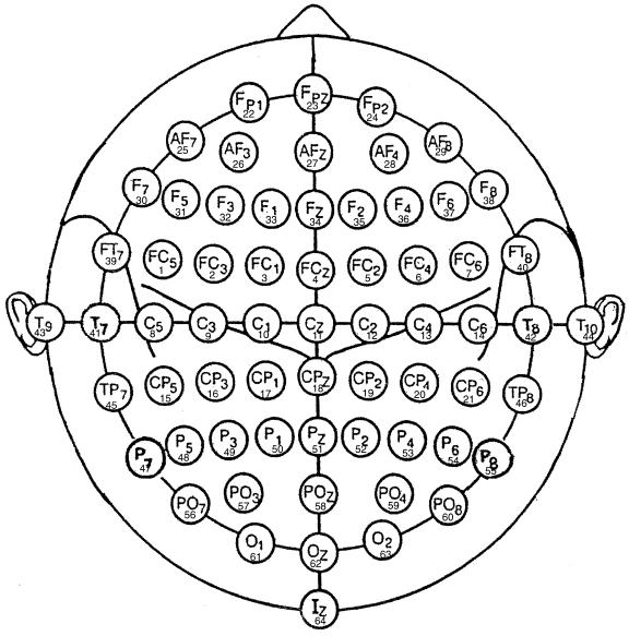
Figure 2: This
diagram illustrates electrode designations (Sharbrough, 1991)
and channel assignment numbers as used in our experiments.
The Signal
For each session (e.g., AA001.mat), the EEG signal is stored in one big matrix signal (total # samples x 64 channels). Other variables define the run number (run), trial number within the run (trial), and sample number within the run (sample). Please refer to Figure 3 for an illustration.
For each trial, events are coded by the variables TargetCode, ResultCode, Feedback, and InterTrialInterval. TargetCode defines the position of the target on the screen (i.e., 0 when no target was on the screen, and 1-4 when a target was on the screen (TargetCode was 1 when the target was on the top)). ResultCode specified the target that was actually selected in online operation (i.e., the class predicted online by the classifier). (For the unlabeled sessions (sessions 7-10), TargetCode and ResultCode were set to –1, whenever they otherwise would be > 0.) InterTrialInterval was 1 when the screen was blank and Feedback was 1 when the user was using his/her EEG to control the cursor (i.e., the time period used online for classification). Please refer to Figure 4 for an overview of the time-course of the paradigm used in each trial and for the relevant variables.
Thus, to get the indices of all samples in a trial specified by cur_trial where the subject controlled the cursor (which can be used as row numbers in the variable signal), one would use the following code:
trialidx=find((trial == cur_trial) & (Feedback
== 1));
Other periods (e.g., the inter-trial-interval preceding each trial, or the period in which the target was on the screen but the cursor was not) are included because they could be used to calculated baseline parameters for each trial.
Figure 3: This figure illustrates the content of each Matlab file (e.g., “AA001.mat”). Channel numbers (e.g., columns in the variable signal (i.e., a matrix of total # samples x 64 channels) correspond to channel numbers in Figure 2. See text for a description of the vectors run, trial, and sample. Additional variables label samples within each trial (refer to Figure 4 for details).
Figure 4: This figure illustrates the time course of
variables that
encode the events within each trial. In
stage 1, the screen is blank. In stage
2, a target appears in one out of four locations on the right edge of the
screen (TargetCode equals one when the target was on the top). In stages 3 and 4, the user produces EEG to
control a cursor vertically so as to hit the target. In stage 5, the cursor either hit (TargetCode equals ResultCode)
or missed (TargetCode does not equal ResultCode) the target. The next trial then starts again at stage 1
with a blank screen. In the unlabeled sessions, TargetCode is –1 in
stages 2-5 and ResultCode is –1 in stage 5 (instead of specifying the
actual target positions).
Demonstration Code
·
featuredemo.m
This program calculates and displays average spectra for each of the four
target locations for a specific subject, session number, and electrode
position.
·
demo.m
This program demonstrates a very simple classifier that uses a particular
training session and uses parameters learned from this session to classify a
different session. Specifically, it uses a training session to calculate the
average band-power for a particular electrode position for each of the four
classes (i.e., target positions) and then calculates three thresholds between
those four means. Subsequently, it uses
these thresholds to classify each trial in a different session.
·
suminfo.m
Lists the average accuracies that were achieved online (by using the linear
equation as described above) for a particular subject for each session and each
run (for unlabeled runs, it will display 0).
Online
Accuracies
|
|
|
|
|
|
Accuracies
(%) |
|
|
|
|
Matlab File |
Session |
1st run |
2nd run |
3rd run |
4th run |
5th run |
6th run |
AVG |
|
AA001.mat |
1 |
43.75 |
59.38 |
46.88 |
65.63 |
59.38 |
65.63 |
56.78 |
|
AA002.mat |
2 |
65.63 |
81.25 |
84.38 |
59.38 |
59.38 |
65.63 |
69.28 |
|
AA003.mat |
3 |
75.00 |
84.38 |
78.13 |
71.88 |
81.25 |
68.75 |
76.57 |
|
AA004.mat |
4 |
68.75 |
68.75 |
87.50 |
78.13 |
78.13 |
71.88 |
75.52 |
|
AA005.mat |
5 |
56.25 |
62.50 |
75.00 |
78.13 |
56.25 |
50.00 |
63.02 |
|
AA006.mat |
6 |
53.13 |
65.63 |
78.13 |
81.25 |
81.25 |
56.25 |
69.27 |
|
|
|
|
|
|
|
|
|
|
|
BB001.mat |
1 |
65.63 |
78.13 |
81.25 |
78.13 |
90.63 |
81.25 |
79.17 |
|
BB002.mat |
2 |
68.75 |
59.38 |
62.50 |
62.50 |
71.88 |
78.13 |
67.19 |
|
BB003.mat |
3 |
71.88 |
78.13 |
78.13 |
78.13 |
84.38 |
75.00 |
77.61 |
|
BB004.mat |
4 |
40.63 |
53.13 |
62.50 |
65.63 |
75.00 |
68.75 |
60.94 |
|
BB005.mat |
5 |
40.63 |
68.75 |
56.25 |
71.88 |
71.88 |
71.88 |
63.55 |
|
BB006.mat |
6 |
78.13 |
71.88 |
68.75 |
62.50 |
71.88 |
65.63 |
69.80 |
|
|
|
|
|
|
|
|
|
|
|
CC001.mat |
1 |
62.86 |
65.71 |
71.43 |
68.57 |
74.29 |
74.29 |
69.53 |
|
CC002.mat |
2 |
62.86 |
65.71 |
71.43 |
68.57 |
74.29 |
74.29 |
69.53 |
|
CC003.mat |
3 |
77.14 |
65.71 |
71.43 |
65.71 |
68.57 |
74.29 |
70.48 |
|
CC004.mat |
4 |
74.29 |
80.00 |
77.14 |
74.29 |
62.86 |
68.57 |
72.86 |
|
CC005.mat |
5 |
62.86 |
62.86 |
54.29 |
57.14 |
57.14 |
74.29 |
61.43 |
|
CC006.mat |
6 |
74.29 |
85.71 |
82.86 |
77.14 |
74.29 |
77.14 |
78.57 |
|
|
|
|
|
|
|
|
|
|
|
REMARK: |
|
|
|
|
|
|
|
|
|
original CC002 was
corrupt |
|
|
|
|
|
|
||
|
CC002.mat equals
CC001.mat |
|
|
|
|
|
|
||
Table 1: This table illustrates the online accuracies
for the
labeled sessions (sessions 1-6). Note
that accuracy would be 25% by chance.
Bibliography
McFarland, D.J., Lefkowicz, A.T. and Wolpaw, J.R. Design and operation of an EEG-based
brain-computer interface with digital signal processing technology. Behav. Res. Methods Instrum. Comput., 1997a,
29: 337-345.
McFarland,
D.J., McCane, L.M., David, S.V. and Wolpaw, J.R. Spatial filter selection for
EEG-based communication. Electroenceph. clin. Neurophysiol., 1997b, 103:
386-394.
Sharbrough, F., Chatrian, G.E., Lesser, R.P., Luders, H., Nuwer, M. and Picton, T.W. American Electroencephalographic Society guidelines for standard electrode position nomenclature. J. Clin. Neurophysiol., 1991, 8: 200-202.
Wolpaw, J.R., Birbaumer, N., Heetderks, W.J., McFarland, D.J., Peckham, P.H., Schalk, G., Donchin, E., Quatrano, L.A., Robinson, C.J. and Vaughan, T.M. Brain-Computer Interface Technology: A Review of the First International Meeting. IEEE Trans Rehab Eng, 2000, 8(2): 164-173.